University team project · James Madison University · 2018–2019
An adaptive human-powered vehicle, designed around one rider
Our nine-person team, 3x3 Amigos, designed and built a human-powered vehicle for a specific client, a JMU kinesiology professor with cerebral palsy. Instead of asking him to adapt to a standard bicycle, we designed around his abilities and goals. I contributed to the mechanical design and took the lead on prototyping, fabricating with arc welding, a band saw, and CNC machining, and helped assemble and integrate the subsystems.
Project status: Team project · chosen as the client's final design · 2019
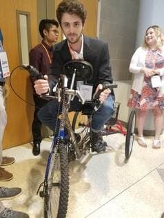
My part in a team build
- Contributed to the mechanical design; detailed 3D models in SolidWorks
- Took the lead on prototyping; fabrication with arc welding, band saw, and CNC machining
- Hands-on integration of the rear disc brake, hand-propulsion chain, and front hand brake (with teammates)
- Testing and iteration as a team member
01The problem
A standard bicycle didn't fit the rider
The brief was one person, not a market: design a vehicle he could ride and operate, around his own abilities and goals.
Our client, Dr. Moran, is a kinesiology professor at JMU. He has cerebral palsy, with weak leg muscles and an out-turned right leg, and he can't operate a standard bicycle. Those constraints had to be designed for, not worked around.
His goals were concrete: ride with his young daughter, get a full-body workout, and travel easily around the city. So were the obstacles: trouble mounting and dismounting a conventional bike, trouble balancing without his cane, tight lower-body muscles, and difficulty carrying heavy objects.
His goals
- Ride with his daughter
- Get a good full-body workout
- Travel easily around the city
Pain points
- Trouble mounting and dismounting a conventional bike
- Trouble balancing without his cane
- Tight lower body; trouble walking
- Can't carry heavy objects
02Requirements
Start with the person
The requirements came from time with the client: what he needed, what he preferred, and what his body could and couldn't do.
Dr. Moran held office hours almost every week, and the team used them. In the first semester we focused on understanding his strengths and limitations and how they affected the early concepts. We took measurements to set the frame's size constraints.
In the second semester we brought him analytical and physical prototypes. He sat on the alpha prototype and told us what he liked and disliked, what was comfortable and what wasn't, and what he could and couldn't operate. Those reactions drove the changes between the alpha and beta builds.
When we couldn't meet with him, we sometimes made decisions on our own, and some of those had to be reverted later. That was the clearest lesson of the project: design decisions about a person need that person in the loop.
Meet
Near-weekly meetings to learn his needs, preferences, and how he's most comfortable positioned.
Measure
Body measurements set the frame's size constraints.
Show
Analytical and physical prototypes brought back to him for reaction.
Try
He sat on the alpha prototype: comfort, positioning, what he could and couldn't operate.
Change
His feedback drove the changes made for the beta prototype.
| Client need | Design response |
|---|---|
| Easier mounting and dismounting | A swivel seat with a step handle in the initial concept (the swivel was later removed). |
| Carrying items, including groceries and his cane | A basket positioned so the load wouldn't greatly shift the vehicle's center of mass. |
| Riding with his daughter | A daughter's seat in the initial concept, later removed as not critical to his goals. |
| Comfortable body position for hand propulsion | A chest rest whose material and dimensions were chosen so it wouldn't interfere with arm propulsion. |
03Architecture
From requirements to a vehicle
Two ways to drive it, several ways to stop it, and a body position built around the rider.
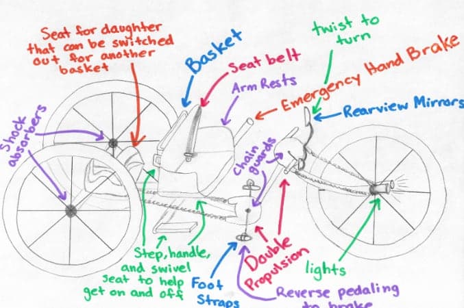
The preliminary concept tried to include everything the client might need. The architecture that carried through was a three-wheeled vehicle with two ways to drive it and several ways to stop it.
- Hand propulsion and steering
- A raised hand crank chained to the front wheel
- Foot propulsion
- Pedals with a geared rear drive and foot straps
- Braking
- Hand brakes with disc calipers, plus reverse-pedal (coaster) braking
- Body support
- Seat and chest rest positioned for combined hand and foot use
- Cargo
- A basket placed with the center of mass in mind, for groceries and his cane
- Safety
- Mirrors, lights and reflectors, and chain guards
04Concept selection
Choosing the concept
Propulsion, safety, braking, steering, and accessibility were weighted by how much each mattered to the client.
Team members brought their designs from the previous semester. We scored them with a weighted decision matrix whose criteria were the vehicle's subsystems, weighted by how much each mattered to Dr. Moran.
Concept A scored highest. We then compared the matrix row by row and carried the strongest subsystems from across all the concepts into the final design: double (hand and foot) propulsion, Concept A's frame, armrests, foot straps, a seat belt, mirrors, and lights.
| Criterion | Weight | A | B | C | D | E |
|---|---|---|---|---|---|---|
| Propulsion | 25% | 1.25 | 1.00 | 1.00 | 0.75 | 1.25 |
| Safety | 25% | 1.25 | 0.75 | 0.75 | 1.25 | 1.25 |
| Braking | 15% | 0.75 | 0.60 | 0.75 | 0.75 | 0.75 |
| Steering | 15% | 0.60 | 0.60 | 0.60 | 0.75 | 0.60 |
| Accessibility | 20% | 1.00 | 0.60 | 1.00 | 0.80 | 0.80 |
| Total | 100% | 4.85 | 3.55 | 4.10 | 4.30 | 4.65 |
| Source | Failure mode | Mitigation |
|---|---|---|
| Tires / traction | Slippage and loss of traction from small tires, poor tread, or low tire pressure | Larger tires with adequate tread; tire-pressure indicator |
| Seat / seatpost | Weight-support failure, loose fasteners, slipping seatpost | Quality fasteners, properly tightened |
| Chain and sprocket | Clothing caught in the chain; chain detaching | Chain guards between drivetrain and rider; chain retention |
| Bolts and fasteners | Fasteners loosening or falling out | Thread-locker; tighten to specified torque |
| Brake system | Brakes or cables failing from rust or wear | Sealed, enclosed cables and connections; quality parts |
05Analysis
Analytical prototyping
CAD, center of mass, and frame forces, used to make decisions before committing to hardware.
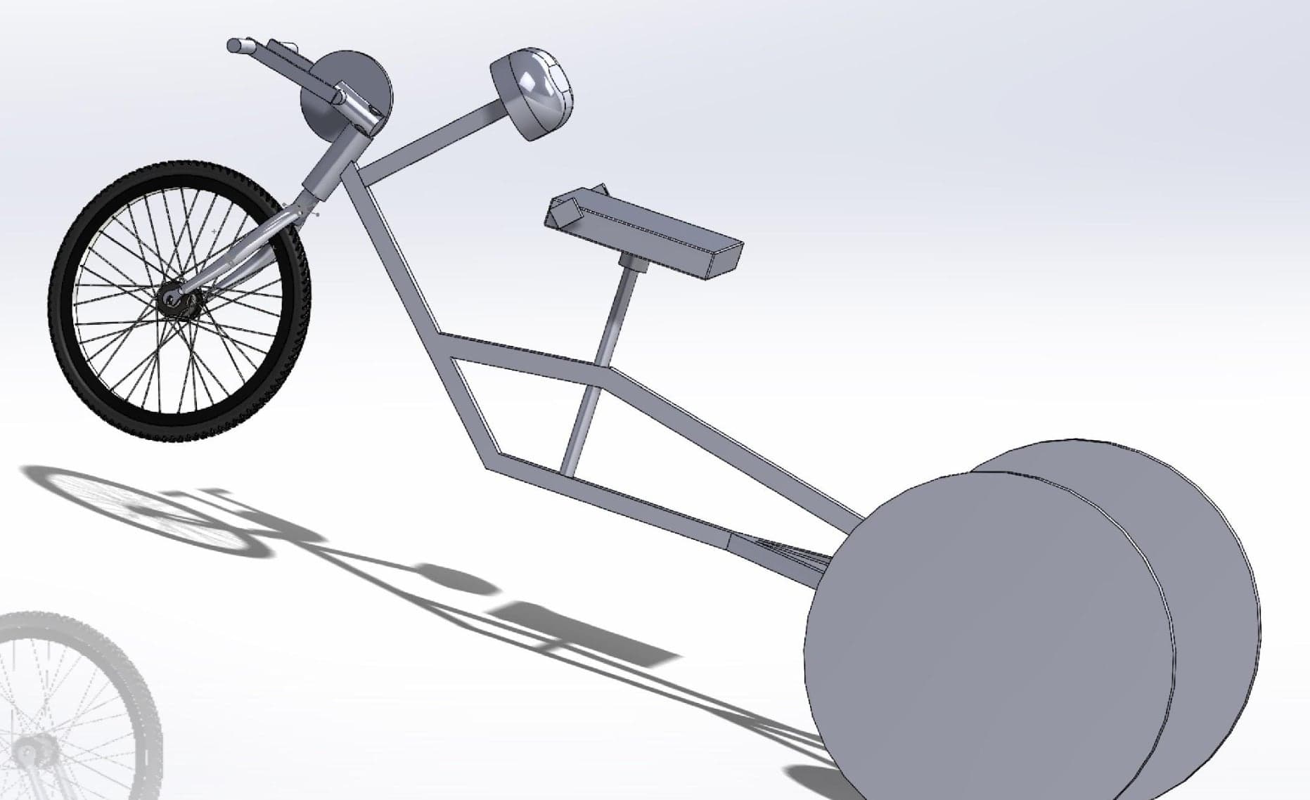
Before cutting tube, we modeled the vehicle in SolidWorks. The assembly let us change the design quickly, count components for the bill of materials, and run material stress checks to look for weak points in the frame.
We calculated the center of mass by hand, then automated it in MATLAB so it could be updated as real component weights and positions came in. With the rider included, the script also estimated the incline and decline angles at which the vehicle would tip.
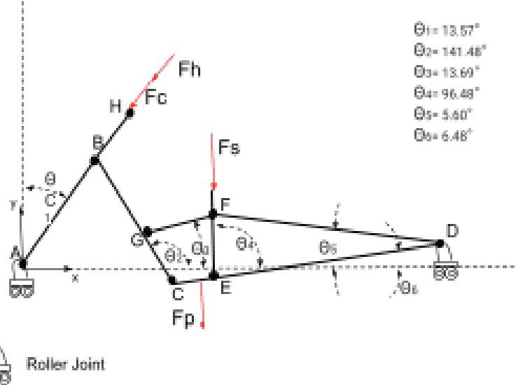
For the frame, we drew a free-body diagram with the rider's weight distributed across the seat, chest rest, handlebars, and pedals, wrote the equilibrium equations for each member, and solved for the reaction forces in MATLAB. The codes were kept current as the design changed.
06Proofs of concept
Build the subsystems first
Each subsystem was proved on its own before it had to work with the others.
A vehicle built around one rider has a lot of interacting subsystems, so we proved them out individually before integrating them.
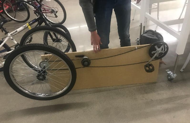
- Foot propulsion and braking
- Taught us how back-pedal braking works and gave a first estimate of the gear ratio.
- Frame
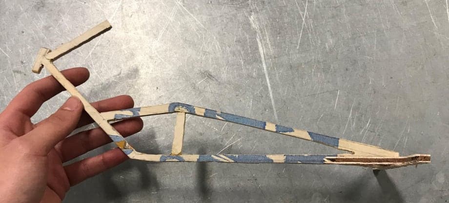
- A one-fifth-scale wooden model, load-tested using water, to estimate how much weight a minimal-material frame could take.
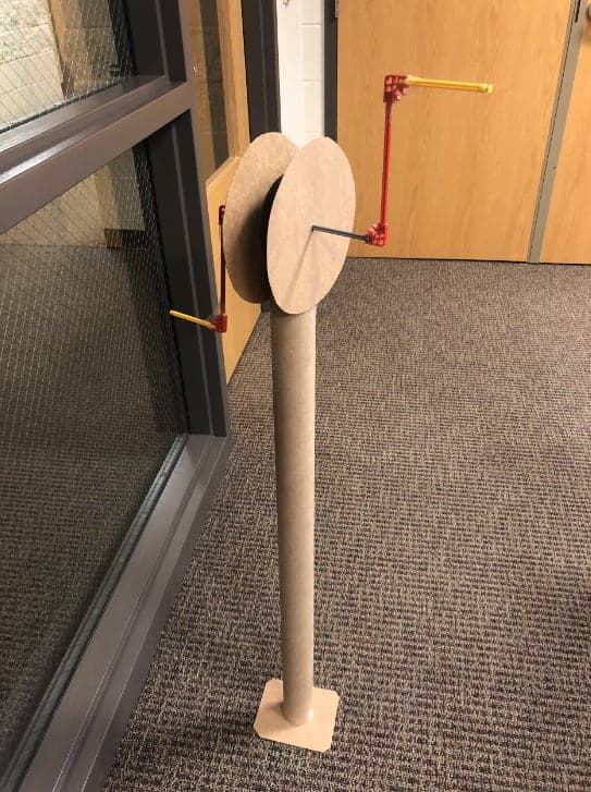
- Hand propulsion
- Checked that hand propulsion would work without interfering with the other subsystems.
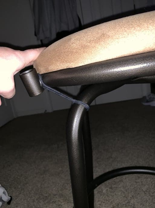
- Swivel seat
- Tested a swivel seat to make getting on and off easier.
- Basket
- Positioned so groceries and a cane wouldn't greatly shift the center of mass.
- Braking
- Aimed to confirm the brakes fit the vehicle and could stop it under heavy load without failure.
- Chest rest
- Compared materials and sizes; chose medium padding and dimensions that left arm propulsion free.
- Pedal straps
- Compared strap designs; a single rubber strap per pedal worked best.
07Alpha prototype
Test what you built
Testing against the team's own criteria showed what worked and what didn't.
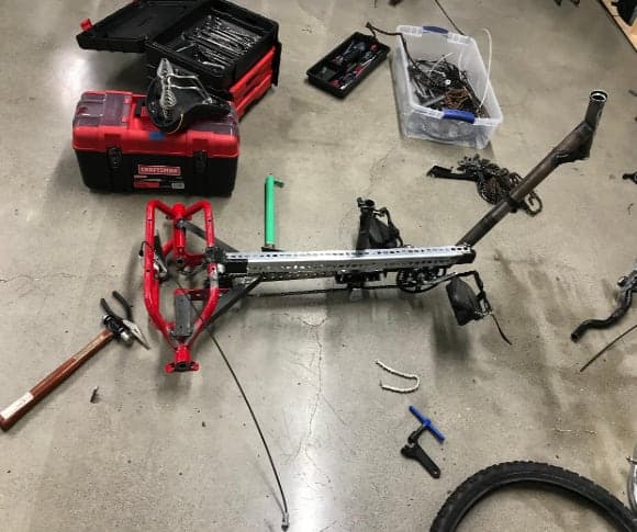
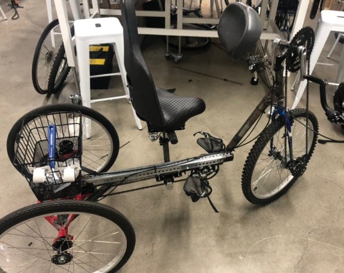
The alpha prototype was built on a salvaged frame. We then ran five tests covering weight, both propulsion systems, and both braking systems, each compared against a criterion the team had set.
| Test | Team goal | Recorded result | Outcome |
|---|---|---|---|
| Hand propulsion | 1 m per crank revolution | 3.165 m (smallest gear) · 4.0635 m (largest gear) | Met |
| Hand braking | Stop in about 2.5–3 s | 4.64 s | Not met |
| Reverse-pedal braking | Stop in about 2.5–3 s | 3.83 s | Not met |
Braking didn't meet its target, and that mattered most, because it's a safety system. The team made changes to improve braking time and safety for the beta build. These are 2019 alpha-prototype results, not validated performance specifications.
08Iteration
What changed, and why
Client feedback and test results turned into concrete design changes for the beta build.
| Change | Why |
|---|---|
| Removed the swivel seat | The seat sat too high for him, so the swivel wasn't stable in use: a safety concern. |
| Removed the seat belt | It restricted his body movement too much. |
| Removed the daughter's seat | It wasn't a critical part of what he wanted from the vehicle. |
| Improved braking | Alpha testing showed stopping times longer than the goal. |
| Frame material, hub type, dimensions | Results from the proofs of concept and alpha testing. |
None of these changed how a whole subsystem operated; they refined features, materials, and dimensions based on the client's feedback, the proofs of concept, and alpha testing. A bicycle expert who supported the course performed safety checks; we made the changes his feedback called for, and the vehicle passed the final safety check.
09Beta prototype
From sketch to beta
Four stages, each shaped by the client and by what the previous build revealed.
Concept
Sketch
SketchPreliminary concept, annotated with the features it tried to include. From the team's 2019 design report. Salvaged frame
Build
PhotographThe salvaged frame the build started from. From the team's 2019 design report. Alpha prototype
Tested
PhotographAlpha prototype. From the team's 2019 design report. Beta prototype
Safety-checked
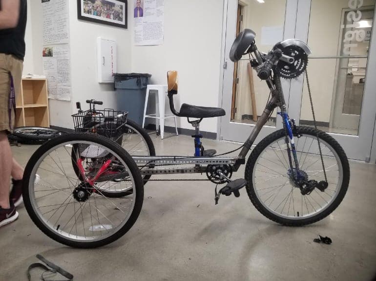
PhotographBeta prototype. From the team's 2019 design report.
The beta prototype brought the iterations together: a vehicle meant to be portable, stable, and simple for Dr. Moran to use every day. At the time of the report, it was to be shown to him for feedback, including his first ride on it.
10My role
My part in a team build
This was a team project. The design was the team's, and the team's accountability record splits every major task (frame analysis, proofs of concept, testing, construction) roughly evenly across nine members. Within that, I took the lead on prototyping.
What I did
- Contributed to the mechanical design and built detailed 3D models in SolidWorks
- Took the lead on prototyping, using arc welding, a band saw, and CNC machining to fabricate a functional proof of concept, and iterated quickly from testing
- Connected the disc caliper to the rear axle, including grinding down the recycled frame
- Connected the hand propulsion to the front wheel, adjusting the chain length
- Connected the front hand brake, with a teammate
- Responsible for the rear wheels in the bill of materials, and shared responsibility for the steel tubing with three teammates
- Took part in testing and iterated on the design from the results
Owned by the whole team
- Client research and requirements
- Concept selection and decision matrix
- Center-of-mass and frame analysis
- Proofs of concept, testing, and construction
11Outcome
What I learned, and where it ended up
Requirements come from the person
Measurements, preferences, and what he could and couldn't operate were the real specification.
Design for real physical constraints
Weak leg muscles and an out-turned leg weren't edge cases; they were core design inputs.
Prototype to learn
Scale models and single-subsystem builds answered questions before full integration.
Assumptions need checking
Decisions made without the client sometimes had to be reverted.
Integration is its own work
Subsystems that worked on their own still had to be fitted, adjusted, and tested together on one frame.
Feedback becomes engineering changes
Client feedback and test results turned into concrete changes: removed features and improved braking.
Dr. Moran chose the 3x3 Amigos design as his final vehicle. A summer intern then took our beta prototype and built it into a finished vehicle for him, implementing most of our design along with a few additions of their own. The fundamentals came from our design.
At the end of the semester, the report had listed the refinements still needed: fine-tuning the seat and chest-rest positions so both hand and foot propulsion felt right, replacing some frame parts with stronger, lighter material, and a more permanent solution for cable management, especially the hand-brake cables.