A personal electromechanical project. I took a knee-traction concept from a cardboard mockup on a leg to a rigid, load-cell-instrumented bench fixture, then tested it under load, investigated what failed, and reworked the part that slipped.
Project status: In progress · bench-tested · no human testing
01Cardboard mockup
Packaging gut check
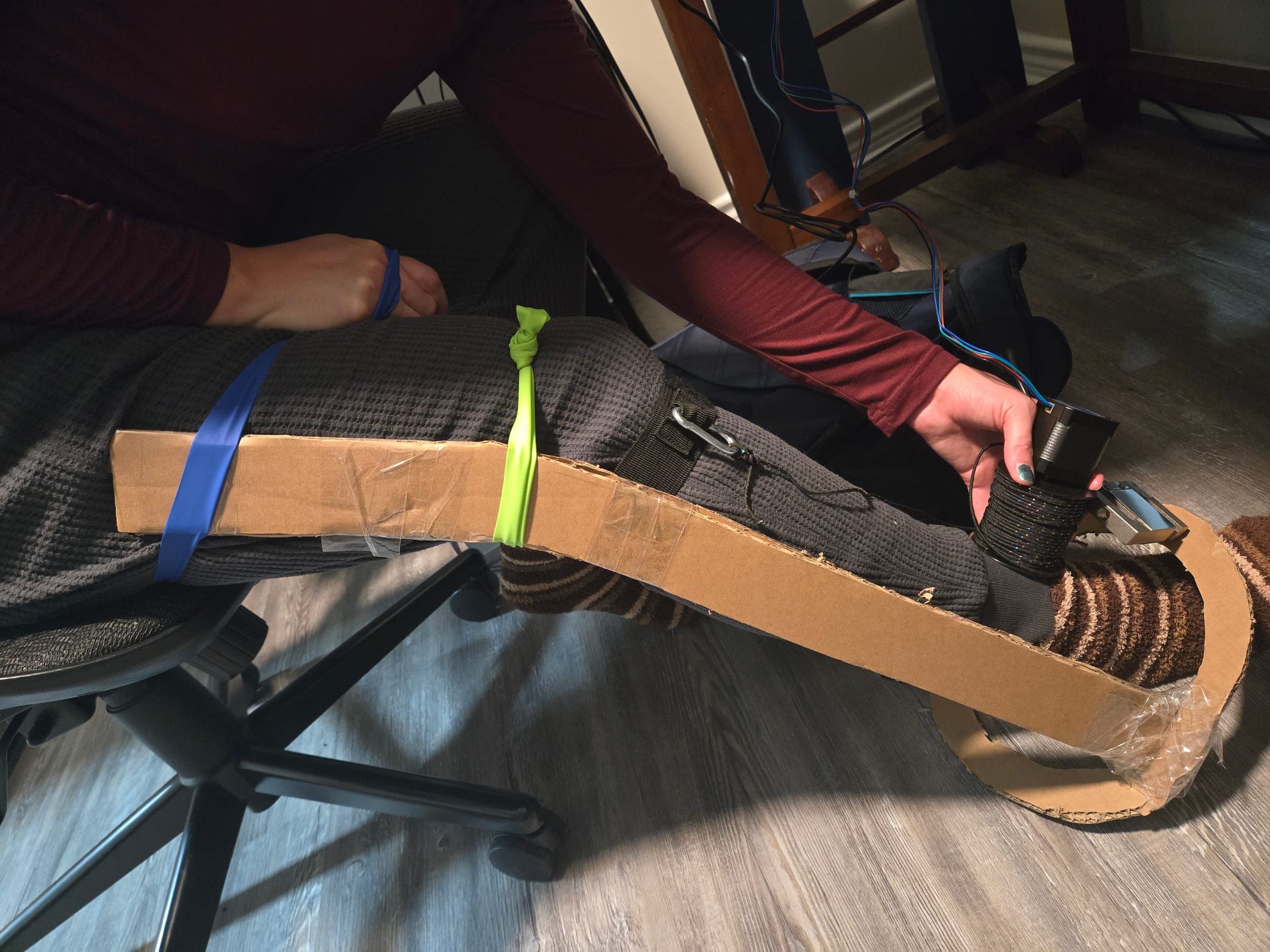
PhotographCardboard mockup on a leg: motor, cord reel, and load cell held at the ankle, with the cord running up to a strap below the knee.
02Fixture concept 1
Built · never tested
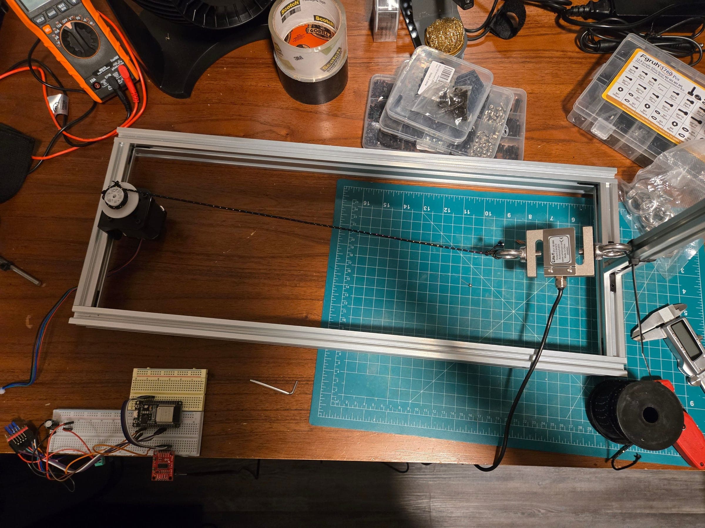
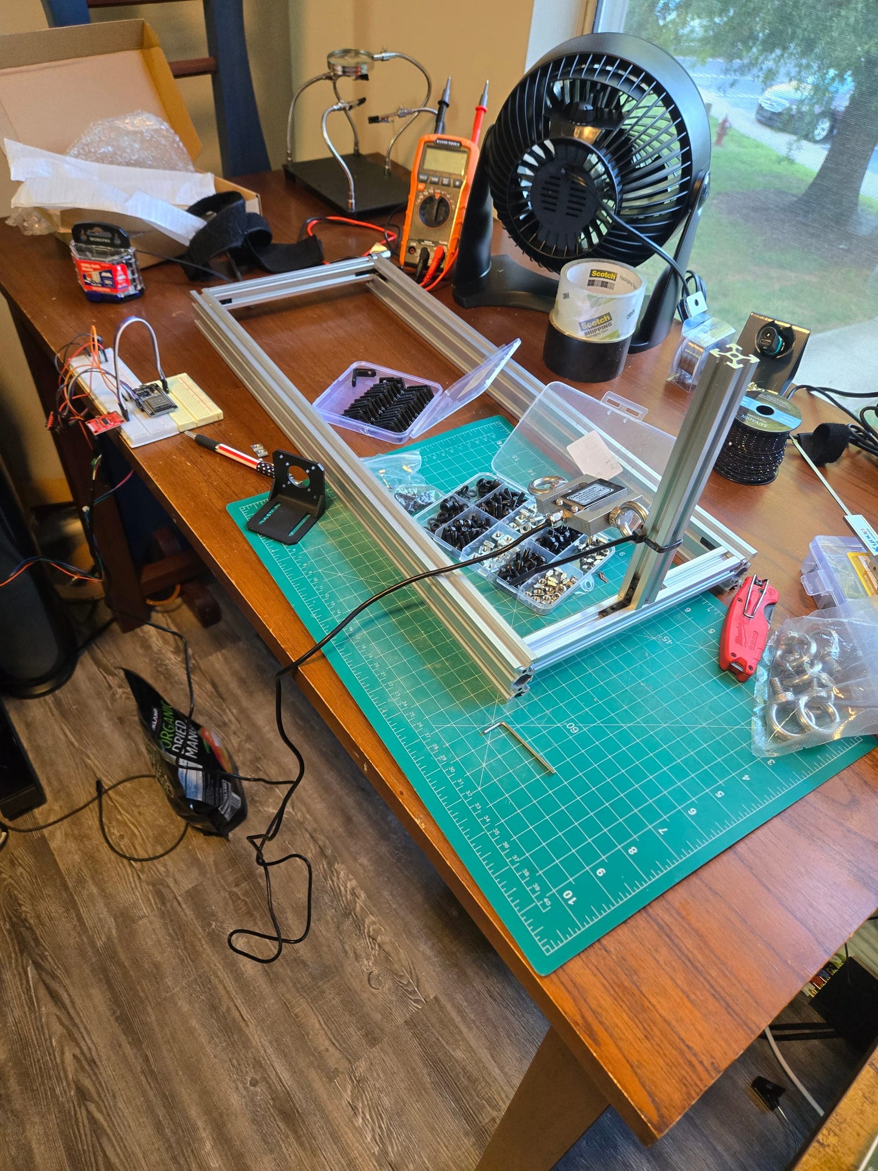
PhotographFixture concept 1: motor and printed spool at one end, cable across the frame, load cell hung on eye bolts at the far end of the cable. Set aside before testing.
03Revised test fixture
Built and tested
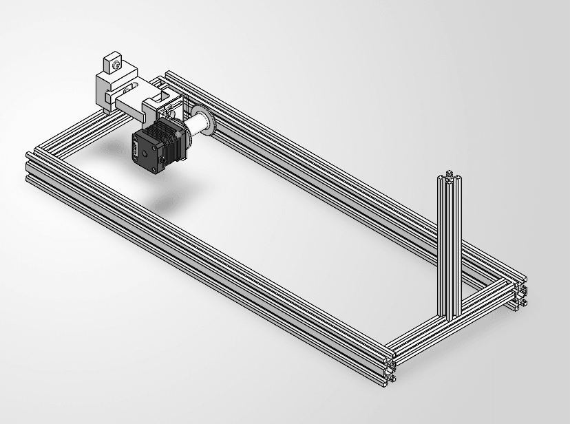
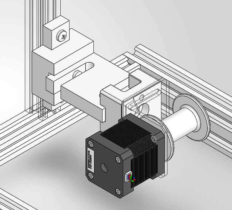
CAD modelRevised test fixture: the load cell sits in the motor's reaction path, between the motor bracket and the rigid upright. Built and tested (photo in section 05).
The long-term goal is a modular wearable system that applies a controlled tensile force for knee traction, with a load cell closing the loop. Development so far is a bench-tested technology demonstrator: I'm proving out the mechanical architecture, the sensing, and the force-control behavior on a fixture, where they can be measured safely, before anything goes on a person.
One of the most useful decisions came early. The first fixture I built didn't represent the system I wanted to test, and I caught that while building it, before running a single test on the wrong architecture.
01The system
One force path, end to end
The whole project is organized around a single load path: a motor at a rigid ankle frame winds a cable onto a spool, the cable pulls on a strap at the knee / upper calf, and a load cell in that path measures the pull so the controller can act on it.
Conceptual · not finalizedTarget wearable architecture
Rigid ankle frame
Load-cell / motor-mount structure
Motor + spool
Cable
Knee / upper-calf strap
Design intent
Keep the load cell's sensing axis as close to the cable's line of action as practical.
Minimize bending moment on the load cell.
Carry motor reaction through the mount and load cell into the rigid ankle structure.
Selected requirements
Closed-loop force control using a load cell
User-selectable force
10–40 lb of traction force
Adjustable for multiple leg lengths
Quick-release attachment
Safety override capabilities
02Physical prototyping
A cardboard gut check before detailed CAD
Before investing in detailed CAD, I built a quick mockup to check whether the motor, load cell, cable, and leg interface could physically fit together, and whether the arrangement made sense around a real leg.
The mockup was deliberately quick and dirty: cardboard, tape, elastic bands, and the real motor, cord, and load cell held in place by hand. It was a gut check on the concept and packaging, a cheap way to see the architecture in three dimensions around an actual leg before committing to detailed CAD. It was never meant to measure performance.
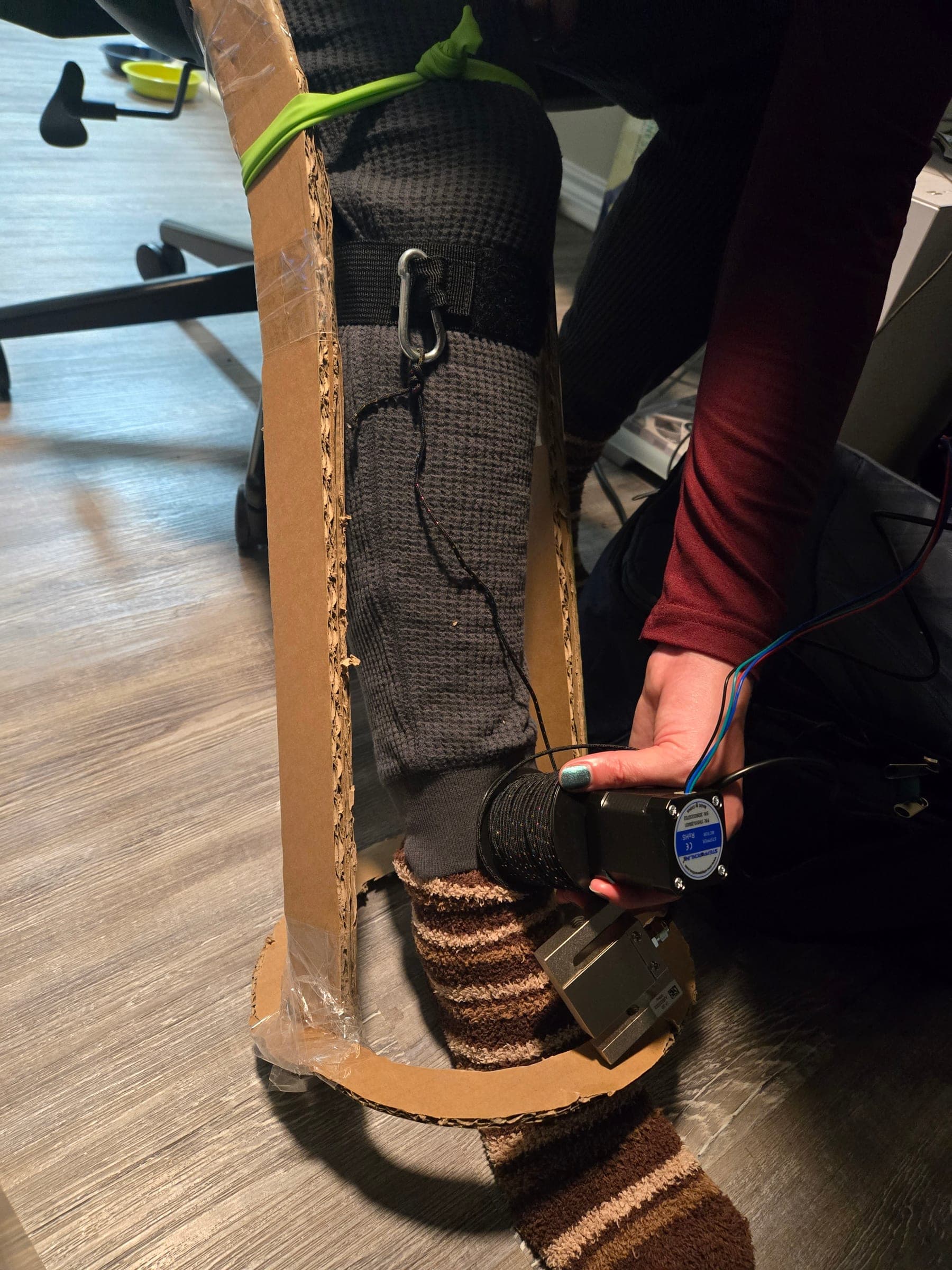
It earned its keep. Putting real hardware against a real leg exposed a load-cell placement problem that wasn't obvious from the conceptual design, and it pointed to the arrangement I've carried forward: motor and load cell together at a rigid ankle frame, with the cable running up to a strap below the knee.
What it checked
Packaging and clearances
Actuator placement
Force direction
Knee-interface concepts
Cable routing
PhotographFront view: the load cell sits with the motor at the ankle ring, and the cord runs to a carabiner on the strap below the knee.
03Fixture design
A first fixture I chose not to test
Building the first bench fixture exposed a representativeness problem before I spent any time testing the wrong architecture.
Fixture concept 1 · built, never tested
To take the leg out of the loop, I built a simplified bench version on a modular aluminum T-slot frame: the motor in a commercial L-bracket at one end, a 3D-printed spool, the cable running across the frame, and the S-type load cell hung between eye bolts at the far end of the cable, anchored to a corner post.
Partway through the build it was clear the simplification had gone too far. The fixture no longer represented the mechanical architecture I actually wanted to develop, so I stopped before running any tests on it.
PhotographConcept 1 during the build: the load cell hangs from the corner post on an eye bolt; the motor bracket isn't mounted yet.
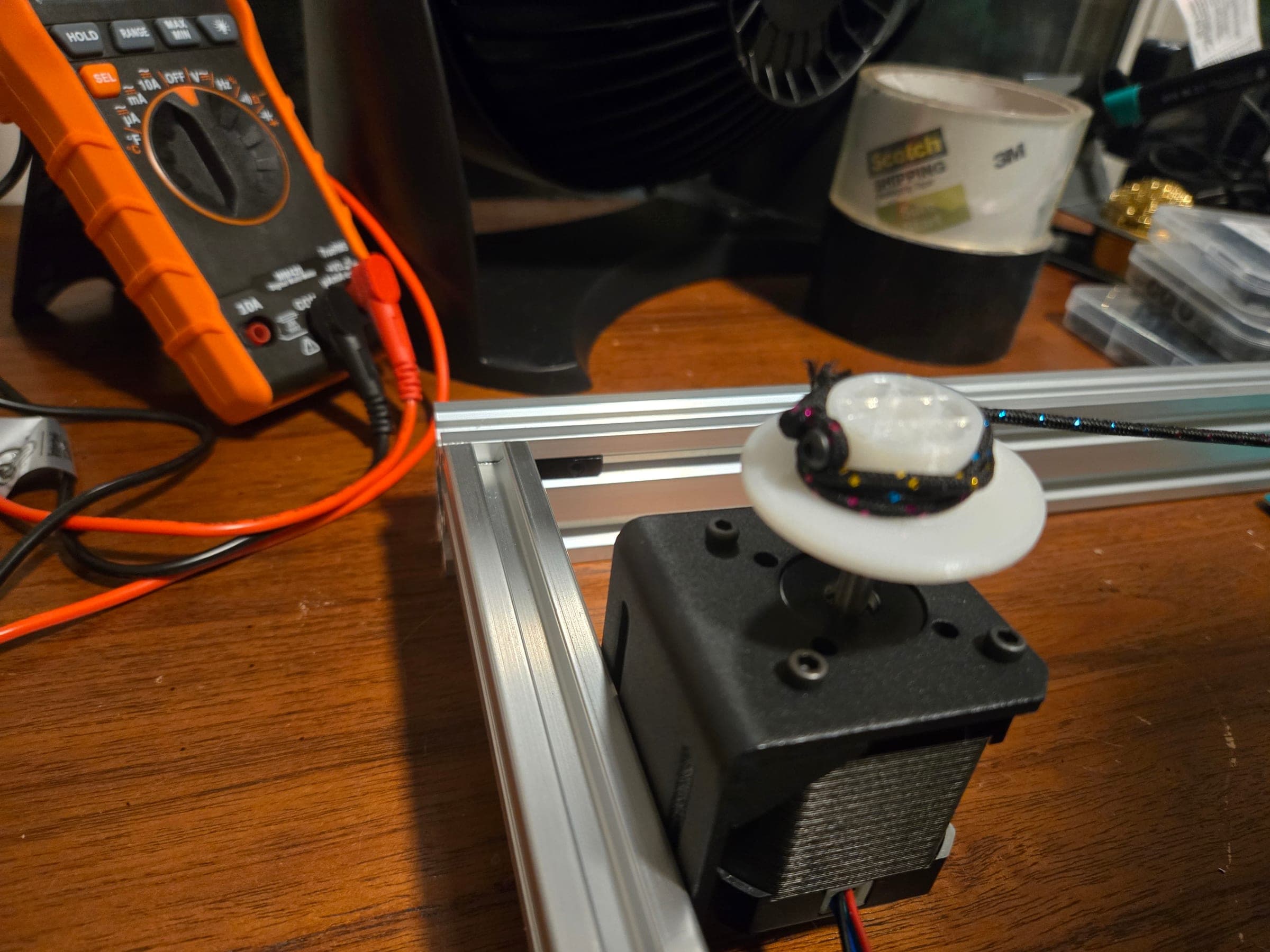
PhotographConcept 1 motor end: a commercial L-bracket and the first single-flange printed spool.
01
Observation
The simplified fixture didn't represent the intended architecture. The load cell sat at the far end of the cable, flexibly positioned on eye bolts rather than rigidly secured, with no controlled geometric relationship to the motor.
02
Design question
How do I reproduce the relevant mechanical force path on the bench, without putting a person in the system?
03
Change
Stop before testing. Go back to CAD and design 3D-printed adapters that put the load cell in the motor's reaction path, the way the mockup suggested.
04
Result
A rigid revised fixture, which became the platform for all of the force-path testing.
03.1
A modular T-slot frame
Constraint
The force path needed to be developed safely before involving a person, with the motor, load-cell, and reaction locations still likely to change.
Options
Desk-clamped fixture
Bolted-board fixture
Top-mounted aluminum T-slot extrusion frame
Decision
A modular, top-mounted aluminum T-slot extrusion frame.
Why
Faster iteration, adjustable component locations, easy changes to the motor, load-cell, and reaction points, and a controlled mechanical force path.
Result
Used for fixture concept 1. The revised design keeps the same rectangular frame layout.
04Design iteration
Back to CAD: adapters for a representative force path
Instead of testing the simplified fixture, I stepped back into 3D modeling and designed adapters and interfaces so the motor and load cell could be mounted much closer to the arrangement I'd explored on the leg.
CAD modelMotor end of the revised fixture: the motor bracket joins a printed adapter, the S-type load cell, and a second printed adapter that fixes the stack to the rigid upright. The spool sits on the motor shaft.
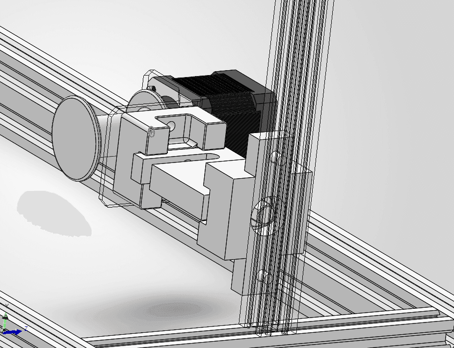
CAD modelSame assembly from the other side, with the upright rendered transparent to show how the adapter bolts to it.
04.1
Redesign the mounts instead of testing an approximation
Constraint
The bench had to reproduce the relevant mechanical force path, not a convenient approximation of it.
Options
Load cell at the far end of the cable (fixture concept 1)
Load cell in the motor's reaction path, between the motor mount and the rigid fixture
Decision
Move the load cell into the motor's reaction path: motor bracket → printed adapter → load cell → printed adapter → rigid upright. The motor's reaction to cable tension now passes through the load cell into the fixture.
Why
A more controlled geometric relationship between the motor and the load cell; a rigidly secured load cell instead of a flexibly positioned one; a bench arrangement closer to the one the mockup suggested; and a measured load closer to the actual applied load in the intended force path, removing potential sources of error.
Result
The revised fixture, which I built and used for all of the testing that follows.
I used an off-the-shelf motor bracket rather than redesigning a commodity mounting component, and put the design effort into the adapters and the spool.
The spool is the other custom part. Its first geometry had significant 3D-printing overhangs, so I redesigned it as two printable halves; one half was enough for early testing. The spool interface is also where the first mechanical failure appeared (section 09).
05Test platform
The revised fixture: the configuration I tested
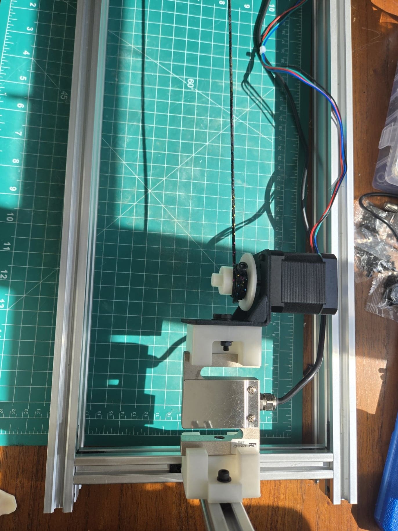
The motor pulls the cable across the fixture, and the motor's reaction to that pull passes through the motor bracket and the load cell into the rigid upright. I designed it in CAD, built it, and ran every force-path test that follows on it.
CAD modelDesigned: the revised fixture in CAD.
PhotographBuilt: the same configuration on the bench. Motor and spool on the off-the-shelf bracket, joined through printed adapters to the S-type load cell, which is fixed to the frame. The cable runs across the fixture to the opposing vertical post, out of frame.
Tested configurationPulling path
MotorNEMA 17
Spoolon the motor shaft
Cableacross the fixture
Opposing vertical postrigid fixture
Tested configurationReaction path: where the load is measured
Motor reaction
Motor bracketoff-the-shelf
Load cellbetween printed adapters
Rigid uprightT-slot fixture
What changed between the two fixtures.
Aspect
Fixture concept 1
Revised fixture
Load cell location
Far end of the cable
Motor reaction path, between the motor bracket and the rigid upright
Load cell mounting
Hung between eye bolts; flexibly positioned
Rigidly secured between printed adapters
Motor ↔ load cell
No controlled geometric relationship
Fixed geometric relationship
Used for testing
No: set aside before testing
Yes: all force-path tests below
06Instrumentation
A force signal established early
The measurement system came first, well before either bench fixture existed.
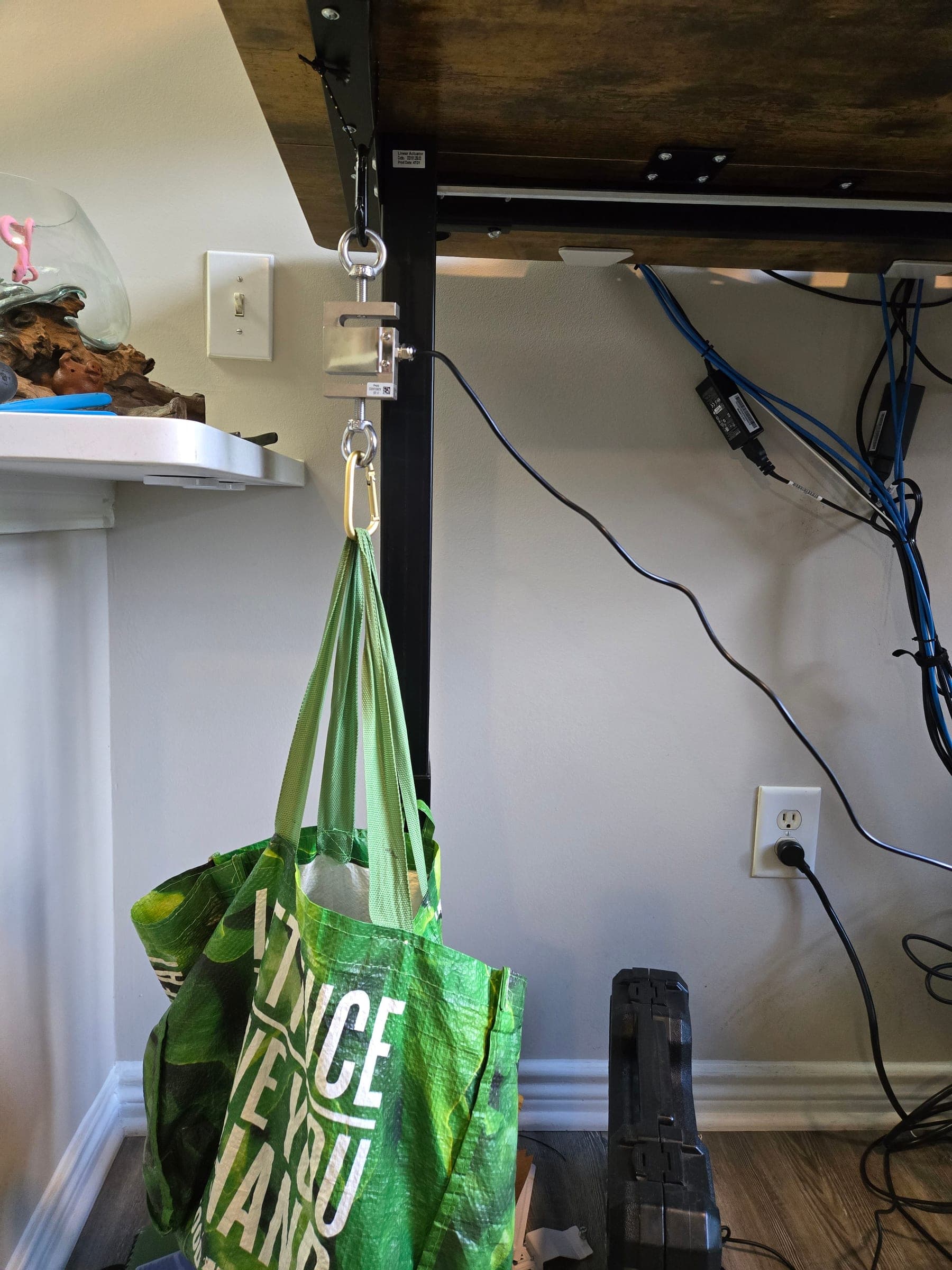
I calibrated the load cell early in the project, before the cardboard mockup and before either fixture, using a dedicated hanging-load setup.
That calibration established the force conversion I carried forward when the sensor was later integrated into the bench system.
PhotographDedicated calibration rig, 9 August 2026: the load cell hung from a fixed point and loaded with household weights, referenced against a bathroom scale.
Recorded linear relationship
raw = 39,570.88 × force(lb) + 12,372.74
Tested range
0–25.4 lbTension.
R²
0.999902Goodness of fit for the line; a fit statistic, not sensor accuracy.
Max residual
≈ 0.135 lbLargest deviation of a calibration point from the fitted line.
RMSE
≈ 0.083 lbOver the tested range.
Conditions and what I did with them
Reference
Bathroom scaleHousehold loads, applied and released between calibration points.
Zero drift
≈ 5,000 → 6,100 countsUnloaded readings with 10-sample averaging over about three minutes.
Decision
Tare separate from scale factorAn unloaded sample during calibration read ≈ 9,800 counts, so zero is handled as its own step.
07Embedded control
Getting sensing and motion to share one loop
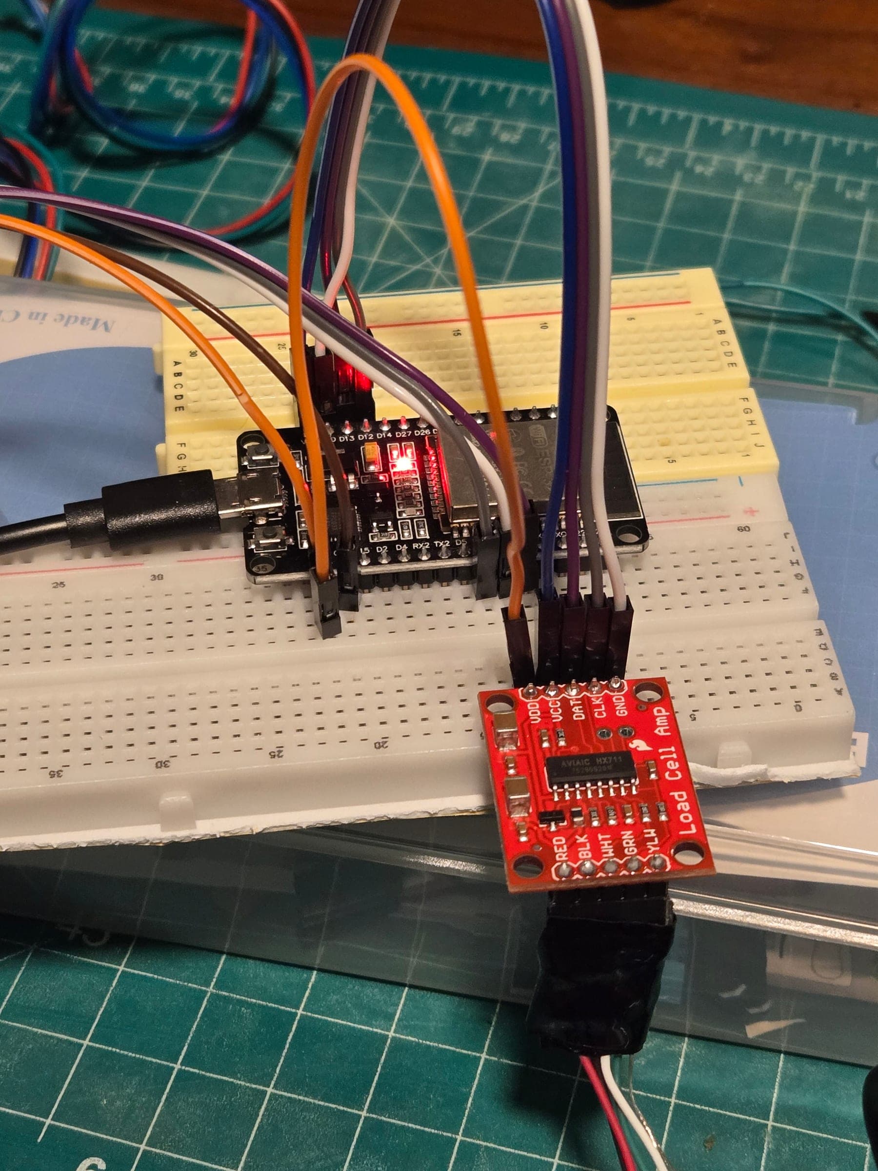
An ESP32 drives the stepper through a TMC2209 driver and reads the load cell through an HX711 amplifier, with motor control and force sensing in separate modules.
main.cpp uses two modules: MotorController, which drives the stepper motor through the TMC2209 driver, and ForceSensor, which reads the load cell through the HX711 amplifier.
Keeping the two modules separate let force readings and motor commands run in the same loop, which is what makes a measured force limit able to stop motion.
PhotographESP32 development board and SparkFun HX711 amplifier on breadboard wiring: development hardware.
07.1
Make force sensing non-blocking
Constraint
The stepper library needs AccelStepper::run() serviced frequently. My first integration used blocking HX711 averaging and unrestricted Serial output, and the motor moved once and stopped.
Decision
A non-blocking update() that checks HX711.is_ready() and takes one available conversion at a time, with force output to Serial throttled to about every 200 ms.
Why
Sensor acquisition and diagnostics were starving the motor loop. Removing the wait and limiting output freed it.
Result
Motor control and force measurement then ran simultaneously.
086 September 2026
First force-limited test on the revised fixture
The motor pulled the cable through the spool, the load cell in its reaction path measured the load, and measured force decided when to stop.
Demonstrated · benchMeasurement and stop path
Load cellmotor reaction path
HX711amplifier
ESP32
Force limitconfigured: 5 lb
Motor stopmotor.stop()
What happened
The motor advanced in small relative steps, pulling the cable through the spool while the load cell, in the motor's reaction path, measured the load.
Measured tension reached the configured 5 lb limit, and the controller stopped the motor.
Tension then released: motor.stop() ends commanded movement, and holding a target force is the next controller to build.
Project requirement
10–40 lb
The traction-force target, with closed-loop force control through a load cell.
Demonstrated on the bench
5 lb stop
Measured force stopped the motor at a configured limit: a complete physical force path from motor to controller.
Next to demonstrate
Holding
Sustained target-force holding, then performance across the 10–40 lb range.
09Failure and redesign
The spool interface slipped
Higher commanded travel exposed a weak point at the custom 3D-printed spool interface.
01
Version 1
Custom 3D-printed spool on a D-feature interface, retained by a set screw.
02
Test
Higher commanded travel.
03
Unexpected behavior
Mechanical slip at the spool interface.
04
Investigation
Inspected the interface: the set screw had stripped.
05
Change
Bored out the feature and installed a larger set screw.
06
Retest
Repeated the 5 lb test. No slipping observed.
10Failure investigation
Tension lost under load: spool or motor?
A separate behavior from the spool slip, investigated on its own. What I saw is kept apart from what I think it means.
Later loaded runs repeatedly lost tension around 4–5 lb. With the spool interface already reworked, I needed to know whether it was slipping again or whether something else was moving.
A mark on the motor shaft separated the two: during failed tests, the shaft itself jumped backward.
Observed
During failed loaded tests, the marked motor shaft jumped backward.
Loaded tests lost tension around 4–5 lb.
With the cable removed, the motor ran smoothly at 250 steps/s.
Interpretation · suspected, not confirmed
Step loss / stall under load is suspected, rather than only a loose spool interface.
The smooth no-load run points the investigation at loaded behavior rather than basic motor operation.
Not established by this evidence
A confirmed root cause
What I varied
Driver VREF
≈ 1.2 V → 1.73 VTMC2209 reference voltage, raised during testing.
Motor current
≈ 1.22 A RMSEstimated at 1.73 V from the recorded BTT VREF relationship, not measured.
Speed
1000 → 250 → 50 steps/s
Force limits
5, 3, 4, 3.5, 3.7 lb
No-load check
Cable removed
11Characterization
Force and speed: specific observations
I recorded loaded behavior at several force limits and speeds on the revised fixture. The points are sparse, so they're tabulated rather than drawn as a curve.
Individual loaded bench observations at ≈ 1.73 V VREF (≈ 1.22 A RMS, estimated), each with only the conditions that were recorded.
Documented conditions
Observed
3 lb force limit
Held successfully.
3.5 lb force limit
Held without abrupt release.
3.7 lb force limit · 250 steps/s
Reached ≈ 4.28 lb during deceleration, then released abruptly.
50 steps/s
Reached ≈ 3.66 lb with no abrupt release; settled near 3.1 lb while maintaining commanded position.
250 steps/s
Reached ≈ 3.9 lb, then lost tension abruptly; settled near 2.1 lb.
Each row lists only the conditions recorded for that observation. These are individual observations, not a controlled test matrix; repeat counts weren't recorded.
“Held” is the wording in the project notes. Closed-loop force regulation is still to be built.
Speed mattered. At 50 steps/s tension settled without an abrupt release; at 250 steps/s it released abruptly. The notebook identifies motor speed as a significant contributor to the load loss. These are a handful of points under specific bench conditions, so they're tabulated rather than drawn as a curve.
A test-method decision that came out of characterization
11.1
Start every run from a measured condition
Constraint
Manual cable slack made each test start differently, and a stepper that stalls can lose physical position.
Options
Visually consistent manual slack
A fixed motor step count
Repeating from the previous failed-test position
Decision
An automatic 1.0 lb force preload after tare, with the setup unloaded before reset and tare.
Why
A force-based preload uses the load cell to establish the actual mechanical starting condition instead of assuming a motor position.
Result
Adopted for bench testing. The lesson: after a stall, commanded steps can't be treated as physical position.
12Status and next steps
Where it stands, and what's next
A working, instrumented bench platform with a documented force path, and a clear list of what comes next.
Demonstrated
Wearable architecture mockup
Revised rigid bench fixture with CAD-designed adapters
Load-cell calibration
Stepper control with non-blocking force sensing
Force-limited stop at 5 lb
Spool-interface rework and 5 lb retest
Loaded and low-speed characterization
Automatic 1 lb preload
In progress
Force regulation and target-force holding
Safety architecture
Actuator force-capability characterization
Wearable mechanical architecture
Planned
TractionController state machine
Programmable traction protocols
Travel limits and sensor-fault detection
Emergency stop / driver-disable path and hard stops
A planned TractionController layer would sit above the existing ForceSensor and MotorController modules.
PlannedIntended user sequence
Select protocol
Adjust permitted parameterse.g. maximum tension
Run
Execute force/time profilestepped, pyramid-style
Safety boundaryDevelopment is bench-only, and human testing has not been performed. Independent force, travel, sensor-fault, emergency-stop, and mechanical-stop protections come before any human-use testing.
Next: force regulation, the safety architecture, fuller actuator characterization, and mechanical refinement, then wearable integration.