Professional work · John Deere · contract engineer through RFA Engineering
A height-of-cut mechanism, from concept to production
I conceived the mechanism and served as the primary designer for the patented subassembly now in production on the John Deere Z998R Diesel ZTrak™ Zero-Turn Mower (opens in a new tab). This is how it went from an idea to production: CAD and GD&T, tolerance and failure analysis, prototypes that failed and stuck, controlled impact testing, and weekly engineering with the supplier who builds it.
Project status: In production · U.S. Patent 12,635,602 B2 (patent PDF, opens in a new tab) · named co-inventor
My role on the subassembly
- Conceived the mechanism
- Primary designer of the patented subassembly
- Owned the CAD and the GD&T
- Detailed mechanical design and tolerance stacks
- FMEA, and the product's official DFMEA
- FEA in SimSolid; test plans and acceptance criteria with test/analysis engineers
- Prototypes, shop, overextension, impact, and field testing
- Weekly engineering with the India-based supplier developing the subassembly
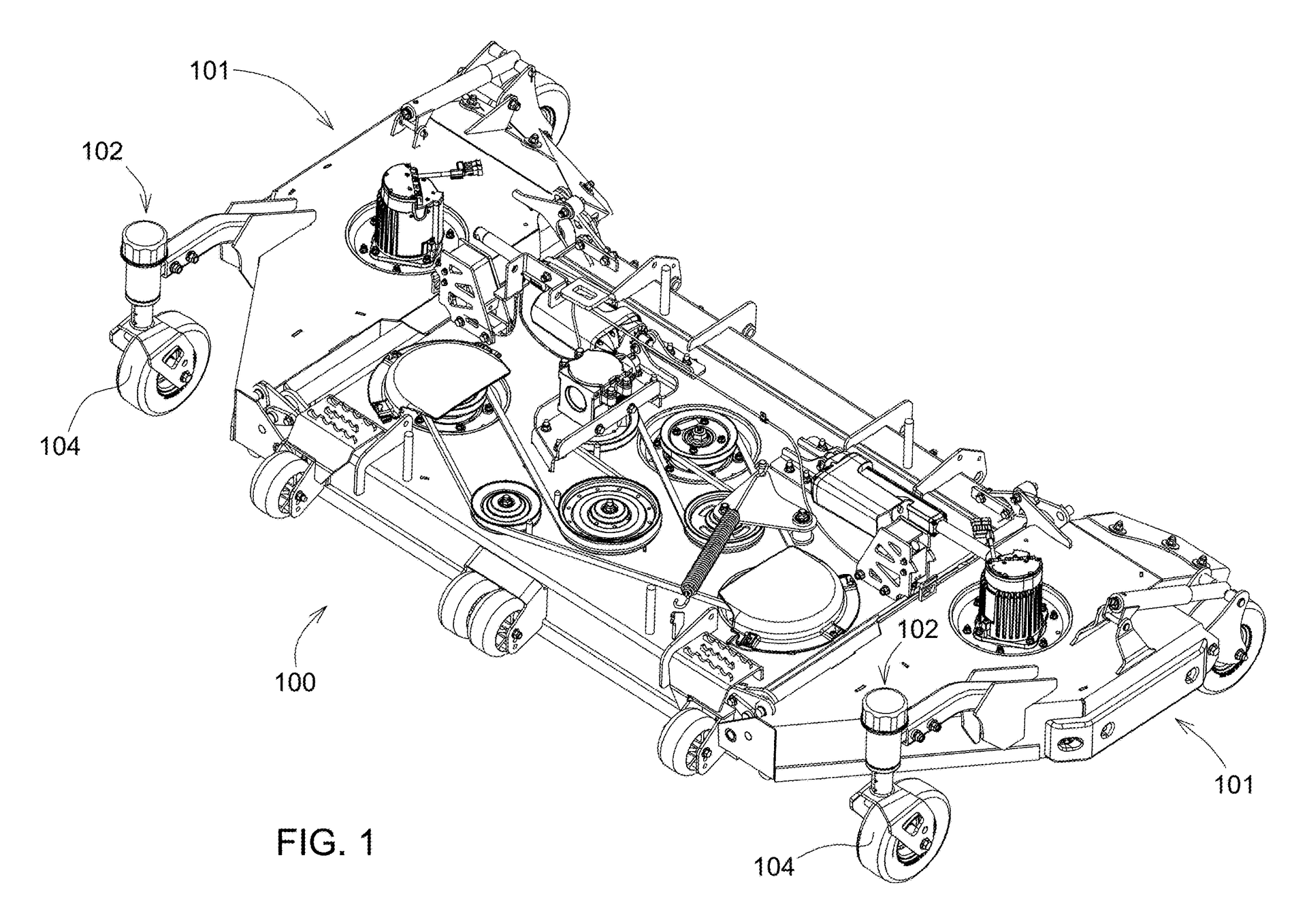
Commercial mower decks are often supported on caster wheels, and the height of cut can be set where those casters mount. The mechanism that sets it has to hold a setting through real use, let the caster swivel freely, and still be easy for an operator to change.
01The problem
A small mechanism with a hard job
Previous approaches, including earlier designs and competitor mechanisms, presented several recurring design challenges.
Pin-hole wear
Adjustment pin holes could wear over time.
Setting vs. actual cut
Wear in the mechanism could make the height setting less consistent with the actual cutting height.
Hard to adjust
Adjustment could be difficult or cumbersome.
Packaging and sightline
The hardware's packaging could restrict the operator's view of the deck's cutting edge.
Customers also wanted to mow beneath low-clearance obstacles, such as solar panels and fences.
The challenge: a height-of-cut mechanism that improves adjustment, durability, height-setting consistency, and operator visibility, while fitting the mower's architecture and supporting low-clearance mowing.
The patent's background states the same needs in general terms: adjusting heavy, caster-supported decks without tools or with easy hand tools, letting casters swivel while the mower moves, improving visibility of the cutting edge, and keeping reliability, serviceability, weight, cost, and part count in check.
Design goals I worked to
- Avoid the wear-prone adjustment interface of earlier approaches
- Keep the setting consistent with the actual cutting height over time
- Easier for the operator to adjust
- Less cumbersome packaging
- Preserve visibility toward the cutting edge
- Support mowing under low-clearance obstacles
- Fit the mower's physical and functional constraints
02The mechanism
Lock the height, keep the swivel
The key idea is to keep two motions separate: setting the height, and letting the caster swivel.
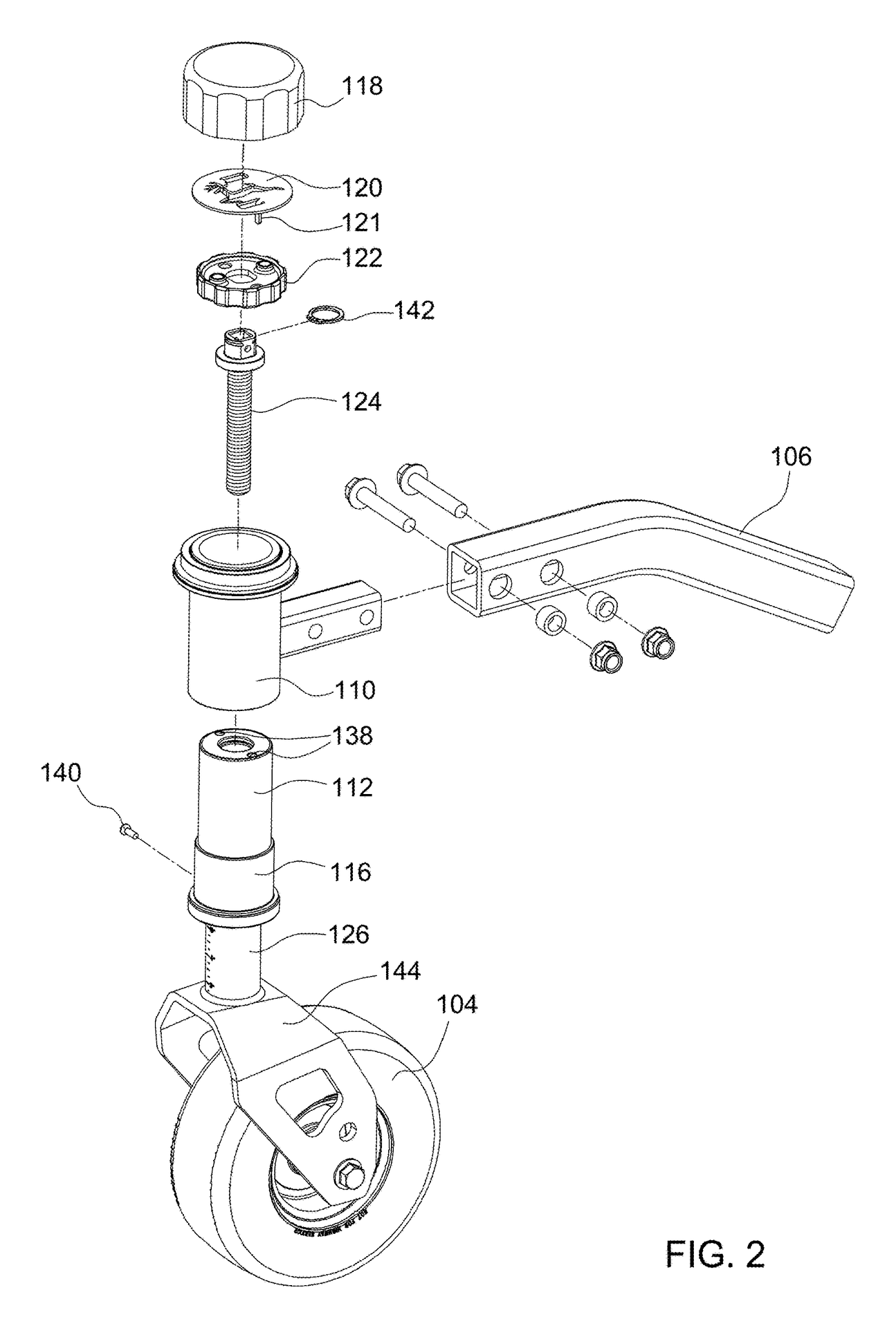
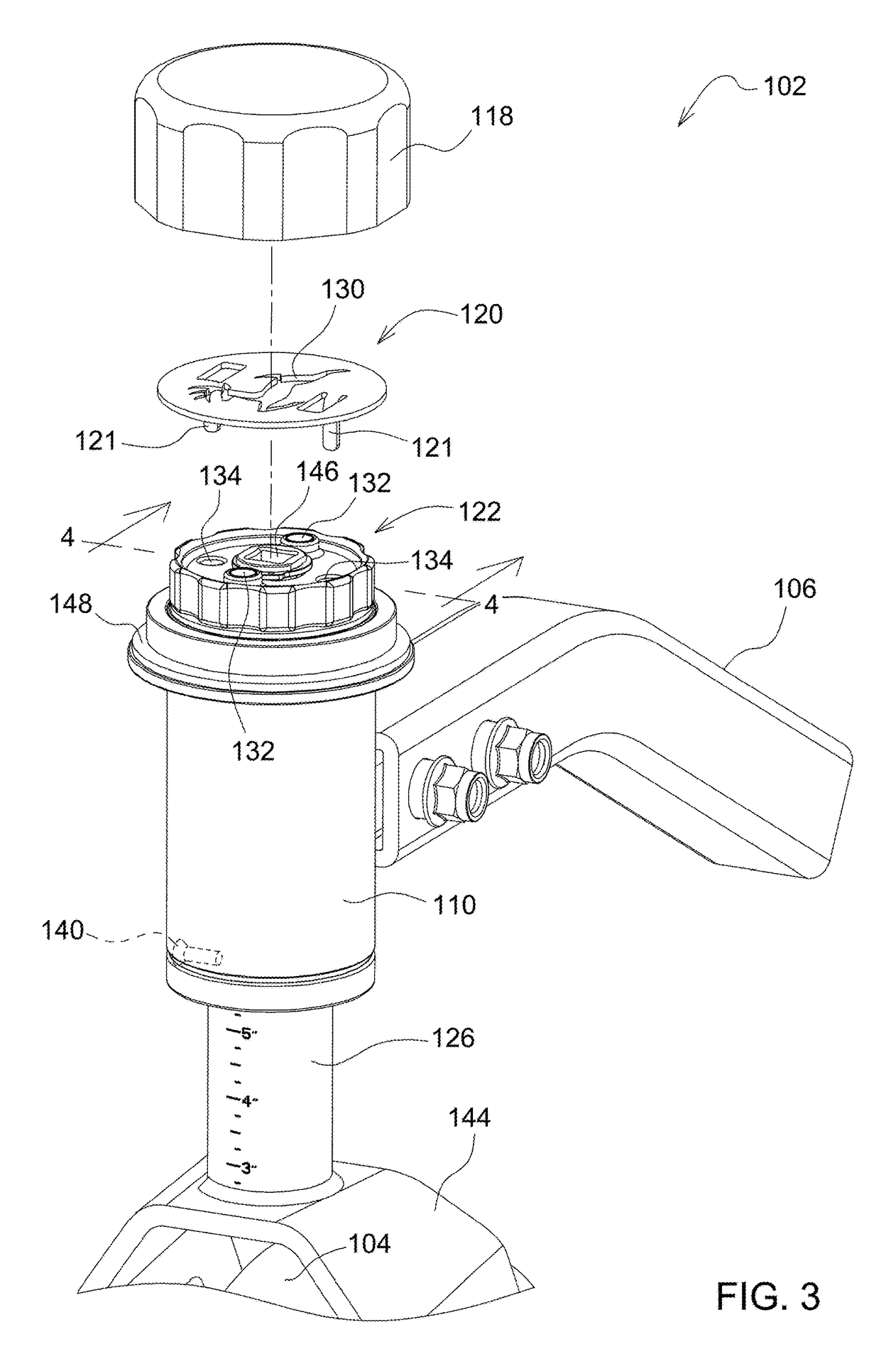
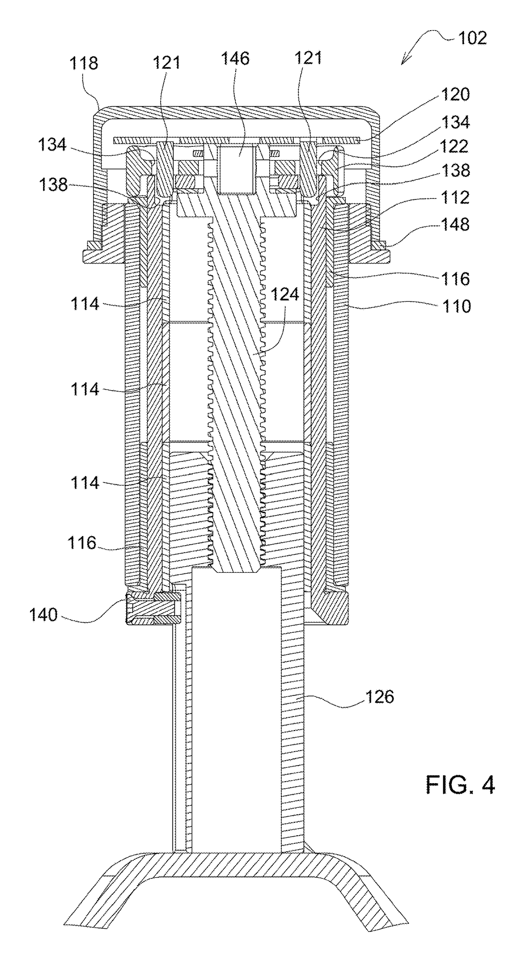
A screw (124) threads into the internally threaded caster shaft (126). Turning it raises or lowers the shaft and the caster, and markings on the shaft show the setting. Instead of selecting a height with a pin in a hole, the height is set by the screw.
To lock the setting, a locking plate (120) drops its pins through the handle (122) into the inner cylinder (112), and a threaded cap (118) closes over the top. The screw is now tied to the inner cylinder, so the setting can't wander.
The inner cylinder sits inside a fixed outer cylinder (110) on bushings and is free to turn. So the locked assembly (screw, shaft, inner cylinder, and caster) still swivels as one. The height stays locked while the caster keeps castering.
To adjust, the operator removes the cap and plate, then turns the handle by hand or drives the socket in the screw head (146) with a ratchet or drill.
- Handle or drill122 · socket 146
- Screw124
- Threaded caster shaft126 · height markings
- Caster moves up or down104
- Caster104
- Shaft + locked screw126 · 124 · plate 120
- Inner cylinder112 · turns
- Outer cylinder110 · fixed
- Arm to deck106
Numbers are the patent's reference numerals. When locked, the plate, handle, screw, shaft, and inner cylinder turn together with the caster; the outer cylinder and its cap stay fixed.
03Detailed design
From concept to a manufacturable design
Turning the concept into something a supplier could build meant owning the details: how each part would be made, toleranced, and assembled.
I did the detailed mechanical design in CAD and owned the GD&T for the subassembly. Tolerance stacks mattered here because the goal was a setting that stays consistent with the actual cut height, and that depends on the variation the design allows.
I took part in FMEA on the subassembly and in the product's official DFMEA, so its failure modes were reviewed alongside the rest of the mower.
I also worked with the testing and analysis engineers to set the test plans and acceptance criteria that both the analysis and the physical tests were judged against.
- CAD
- Owned
- GD&T
- Owned
- Tolerance analysis
- Tolerance stacks
- Failure modes
- FMEA · product DFMEA
- Analysis
- FEA in SimSolid
- Validation planning
- Test plans and acceptance criteriaWith testing/analysis engineers.
04Analysis
Designing against failure
Analysis and physical testing worked together: SimSolid for the loads I could model, and hardware to check the design for real.
I ran FEA in SimSolid for static and impact loads and checked the factor of safety, then confirmed the design on physical hardware.
The most useful analysis came out of a failure. During overextension testing, a custom key-like component failed when the mechanism was driven with a powerful impact tool. To dig into it, I built an Excel calculator around the variables that governed the key: its geometry and its material properties. I could swap materials, heat-treat options, and geometry, and get a pass or fail for each combination.
To check that the calculator was representative of real life, I made a couple of the options quickly in the shop and tried them. Nothing long-term, just enough to see that the hardware behaved the way the model said it would.
The answer was clear: within budget, no combination of material, heat treatment, and geometry would fully withstand the impact tool. So instead of strengthening the key, I changed how the overextension stop worked. Because we had calculated the options and tested a couple of them, we could commit to the new design with confidence.
Observed failure
A custom key-like component failed during overextension testing with a powerful impact tool.
Governing variables
Material, cross-sectional area, geometry constraints, and heat treatment.
Parameterized calculator
I built an Excel calculator around those inputs, with a color-coded pass or fail for each combination.
Quick shop checks
Made a couple of options in the shop to confirm the calculator matched real hardware.
Finding
Within budget, no option would fully withstand the impact tool.
Change
Changed how the overextension stop worked instead of strengthening the key.
05Physical testing
Building and testing hardware
There were many prototype and build cycles. Testing ranged from quick checks in the shop to instrumented impact tests and field use.
| Test | What I did | What it was for |
|---|---|---|
| Quick shop tests | Fast checks on prototypes, on my own and with a teammate | Early checks of prototype behavior |
| Overextension | Overextended the mechanism, including with a powerful impact tool | How and where it fails under overextension |
| Controlled impact | Drove the mower into a curb and controlled objects at varying speeds, with an accelerometer and camera recording | The mechanism's response to impact loads |
| Field testing | Drove and tested the mower at field sites; helped assemble it and did light shop work | Behavior in real use |
| Customer feedback | Gathered operator feedback on ergonomics, ease of use, and intuitiveness | Usability of the adjustment |
Test speeds, measured accelerations, and results are internal and aren't shown.
06What the hardware taught
When the swivel stuck
Physical testing exposed something the design assumptions hadn't.
Assumption
Plastic bearings, intended to run grease-free. The supplier expected the arrangement to work.
Test
Physical testing of the prototype swivel.
Observed
Rotation could stick.
Change
Moved to a sealed, greased bearing arrangement.
Analysis and supplier experience both mattered, but the hardware showed what the assumptions hadn't: in this application, the grease-free arrangement could stick. That's the case for building and testing early.
07Product development
Engineering across the product
The engineering didn't stop at CAD. Getting the subassembly into production meant working with the people who would build, test, and use it.
- Supplier development
- An India-based supplier developed the complete patented subassembly. I held weekly engineering meetings with them covering FMEA, engineering issues, and drawing compliance.
- Sub-suppliers
- Sourcing, component test data, and compatibility with the intended operating environment.
- Fabricators
- Worked with skilled welders and machinists.
- Test and analysis engineers
- Test plans and acceptance criteria for analysis and physical testing.
- Operators
- Feedback on ergonomics, ease of use, and intuitiveness.
Part of broader commercial mowing work
The height-of-cut mechanism was one part of a broader body of work. Over my time at John Deere, I contributed to several commercial mowing platforms and product lines, including zero-turn mower programs and wide-area mowing equipment, as well as other mower subsystems. That work was shared with the wider engineering team, so it isn't written up here. Several of the parts I conceived and designed made it into production; the height-of-cut mechanism is the one this page covers.
08Outcome
In production, and patented
The mechanism is in production on the John Deere Z998R Diesel ZTrak™ Zero-Turn Mower (opens in a new tab).
Z998R on deere.com (opens in a new tab)
I conceived the mechanism and served as the primary designer for the patented subassembly, and I'm a named co-inventor on U.S. Patent 12,635,602 B2 (PDF, opens in a new tab).
- Title
- Mower Deck Height of Cut Adjustment Mechanism
- Assignee
- Deere & Company
- Filed
- May 24, 2023
- Granted
- May 26, 2026